Procedure

Design
We first used Fusion 360, a Computer Aided Design (CAD) tool, to design our sensor. We dimensioned each part to use, then drew up the design, combined the parts together into an exploded view, then downloaded each 3D printed part as a .stl file to send to the 3D printer.
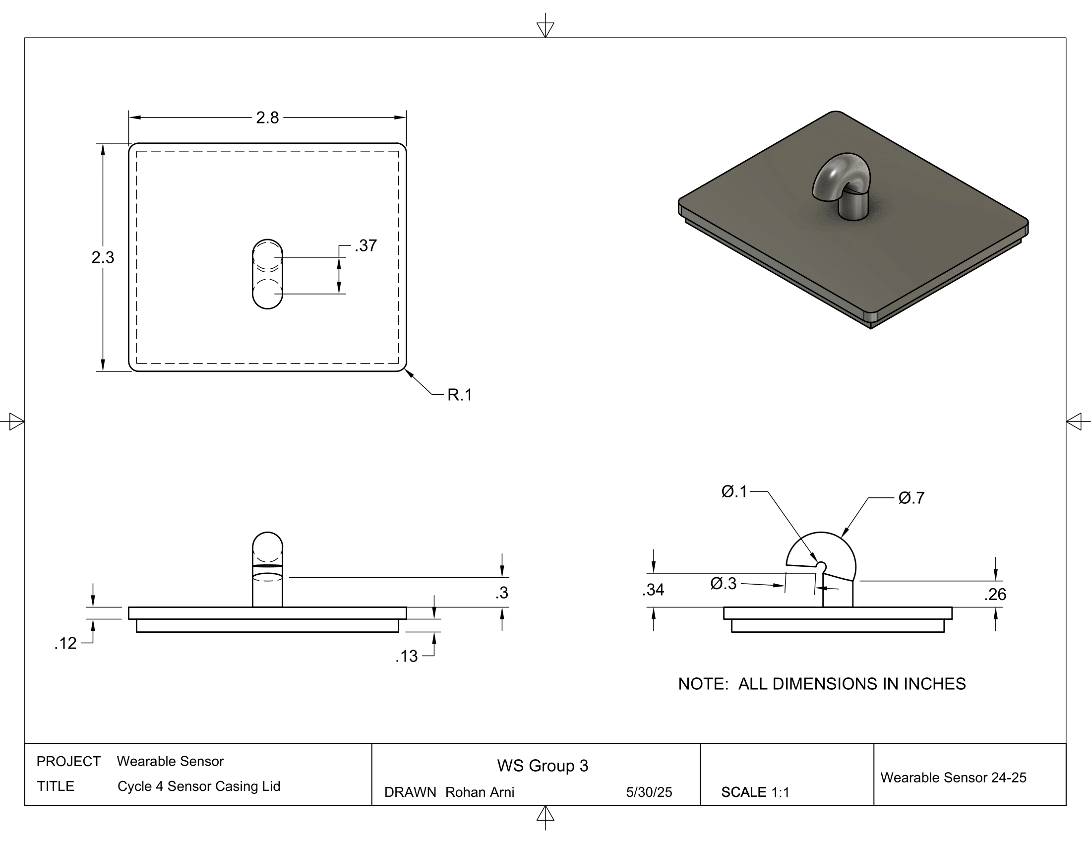
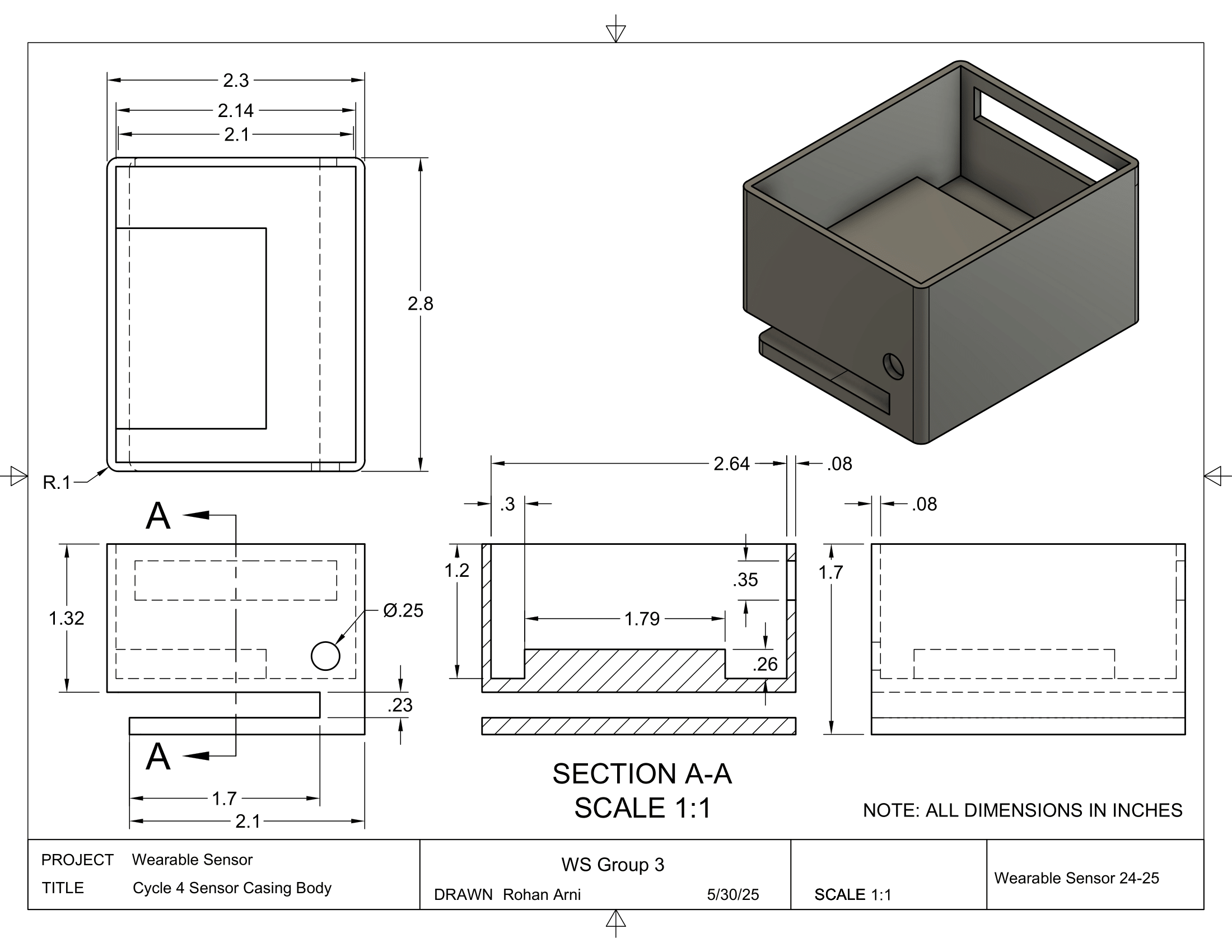
The exploded view of the sensor design, and the sensor casing.
Hardware + Circuit
For our circuit, we used Fritzing to design the circuit schematic. For our parts, we 3D-printed the sensor casing and lid, and used an Arduino Nano 33 IoT for the microcontroller. We also used a capacitive sensor to detect blinks, and used the on-board Wi-Fi module to send data to the user's computer.
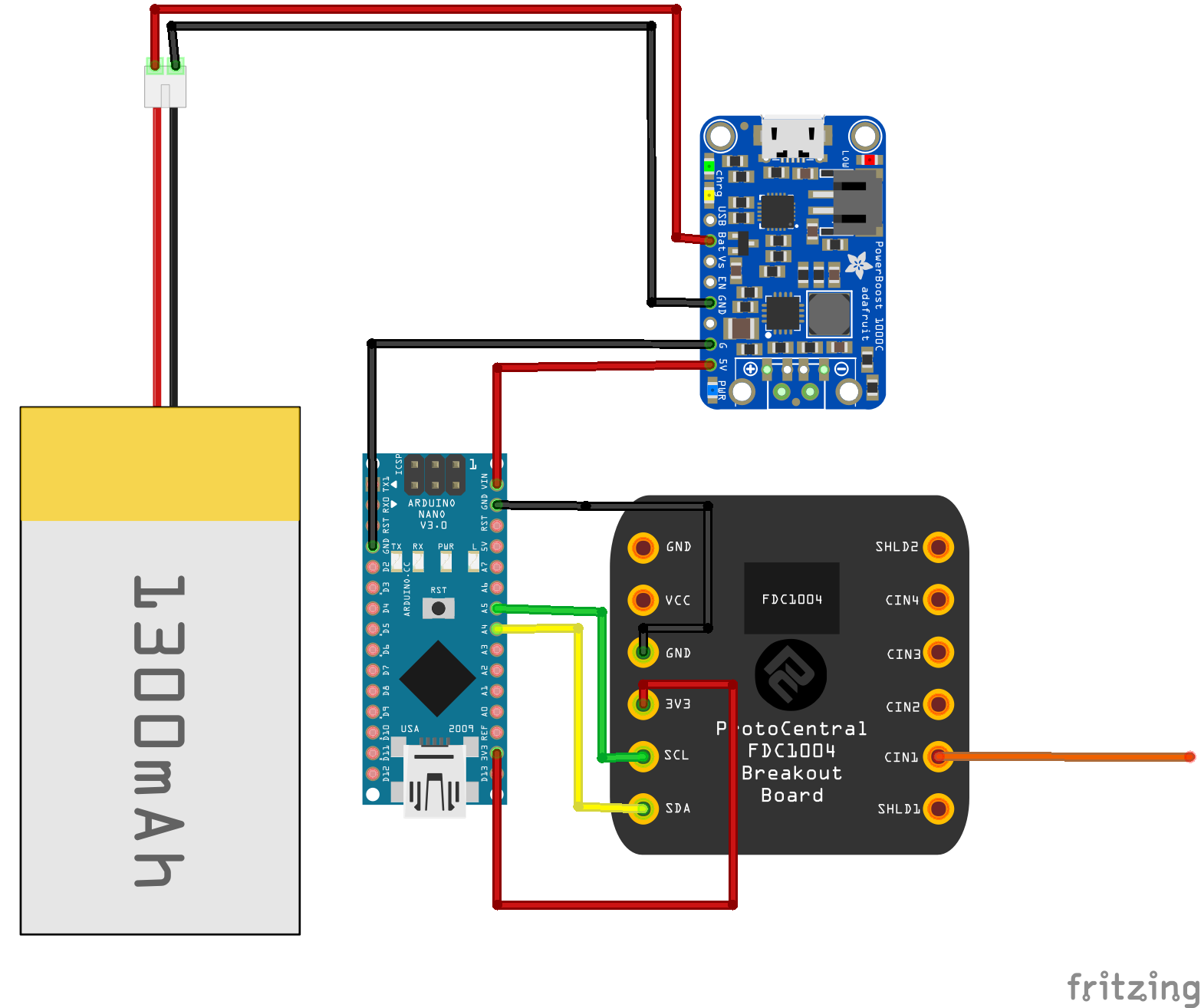
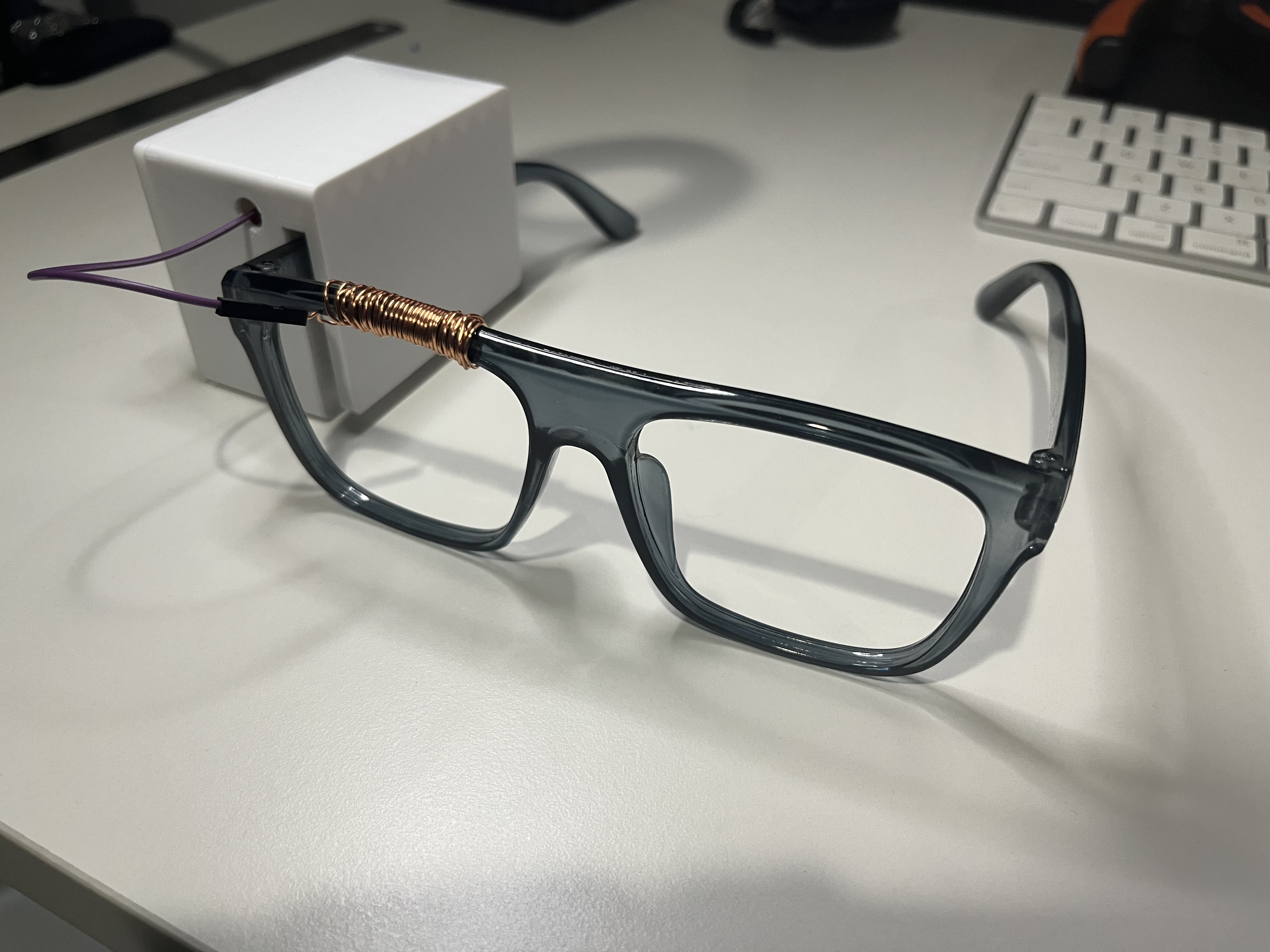
The current prototype of our Arduino and our wearable glasses. Circuit schematic included above.

Arduino Code
Once the wearable sensor begins running, the Arduino runs C++ code to take the capacitance sensor data. This data is then sent to the user's computer, where the Python library numpy is then used to implement a Fast Fourier Transform (FFT) to detect blinks.
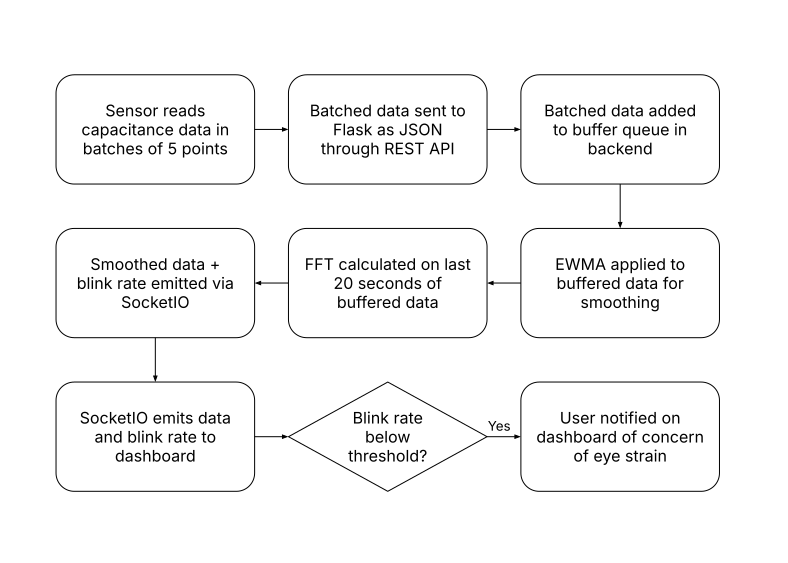
The workflow of the Arduino code, from reading the sensor data to sending it to the computer.

Website & Flask
The code is finally sent to the website, where the data is sent to a Firebase server and then plotted onto the screen with ChartJS. The website itself is designed with Bootstrap, a common HTML library used to create stylish websites; and Flask (with Jinja2), a web application framework used to deploy websites quickly and easily.
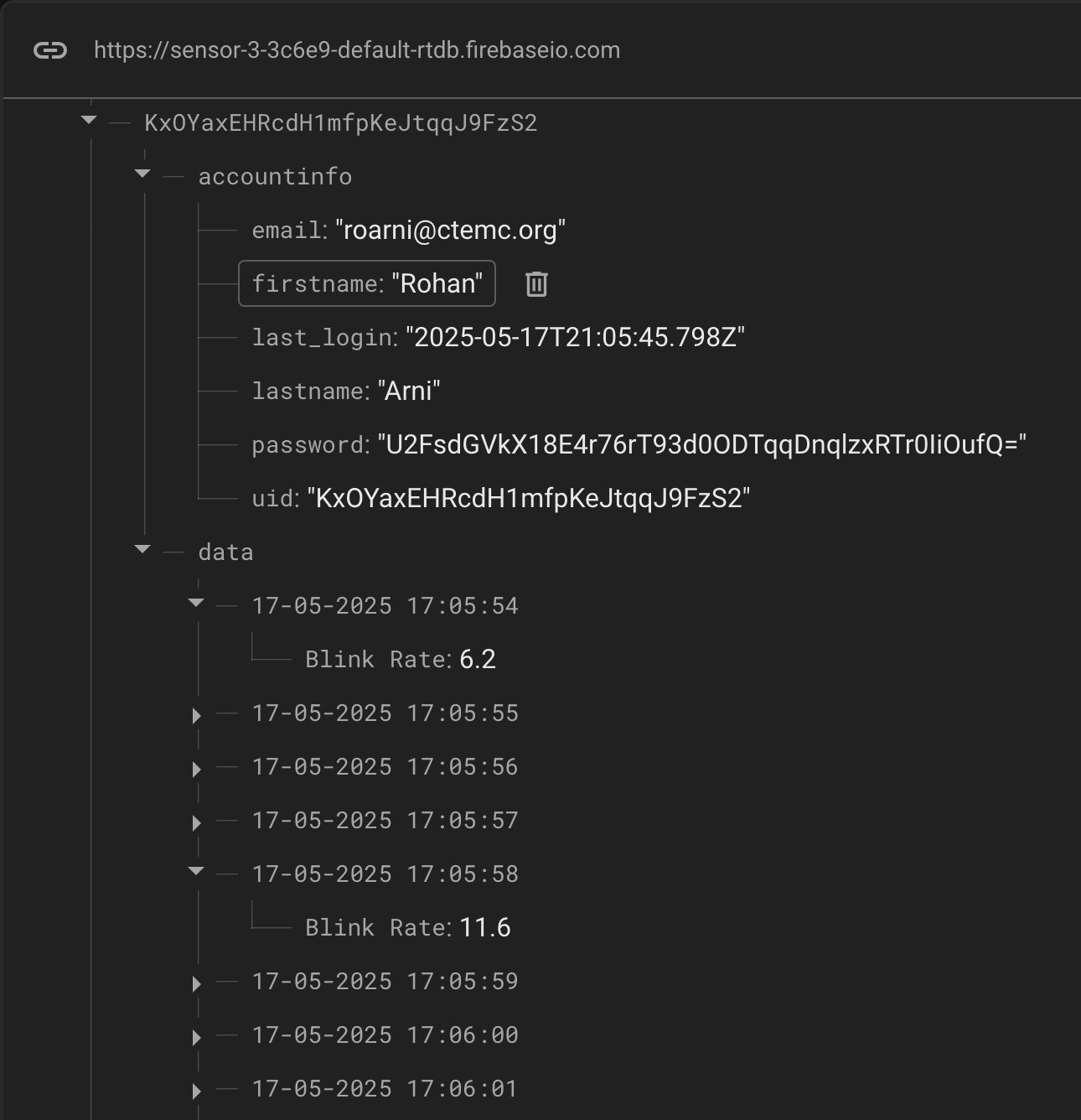
A user on the Firebase website.